Worldstate.de

Welcome to Worldstate Organisation an idea-compilation, it should give an impuls to inventors, scientists and politicians and if nothing works out I hope someone has a follow-up idea.

Worldstate, Estado Mundial, Etat mondial, Weltstaat, 世界状态, विश्व राज्य, мировое государство, العالم , 世界国家, negara dunia, عالمی ریاست, estado ng mundo, বিশ্ব রাষ্ট্র, thế giới, dünya devleti, รัฐโลก, stan światowy, stato mondiale, 세계 상태, Jimbo la Dunia

Nelson Mandela World State

CV Markus Schrems.pdf


Espanol(Spanish)

Francais(French)

Deutsch(German)

Português(Portuguese)

中文的(Chinese,Mandarin)

भारतीय(Indian/Hindi)

Русский(Russian)

(Arabic)عربى

日本(Japanese)

Bahasa Indonesia(Indonesian)

(Urdu)اردو

Pilipino(Filipino)

বাংলা(Bengali)

Tiếng Việt(Vietnamese)

Türk(Turkish)

แบบไทย(Thai)

Polskie(Polish)

Italiano(Italian)

한국인(Korean)

Suaeli(Suaheli)

English

I present my project called „Worldstate“. In an (electronic) money-system that is not correspondant to economic progress the government creates money to pay companies for collective performance, which they have to proove. No infaltion. With seperation in theoretically unlimited government-money to afford all necessary infrastructure especially in 3rd world, renewable energy(faster than E.U.-Plan 2050) or space populating and civilian money which includes 5.000$-10.000$ average salary monthly, unemployment benefits 2.000$, health insurance, pension/retirement money... (social system of Austria). Fixed prices at european level. This would accelerate development, give us the time to controll environmental problems and minimize poverty and crime. The states would stay regulation districts and democracy the political system. World parliament. Then we would all work together and be limited only by the resources; resource-management! No pressure to succeed. Anyone could build up something with 20 years of hard work.

Can these rights be sued through human rights, for example the right to fair payment, the right to pollution reduction/alternative fuel, the right to the best system for fast development, the right to freedom from inflation and wealth through actual economic growth; fraud for wealth, right to fairness for the 3rd world, right to populate space; Contradiction: more money through economic growth but inflation destroys that, capping-principle; doesn't inflation come about, among other things, through comparison with other currencies and economies? The evolution of the system has developed like this, but don't we have more options with another system...all the projects that can't be funded now but would be necessary. Doesn't this monetary and economic system force us for example with ongoing economic groth; let's dominate it!

Simple but good. The dynamics of the current monetary/economic/market system are too complicated even for experts.

Is the debtsystem of countries better?! 100 year old debts. Not any country can pay that back, only paying the interest rate of the debt!

Wikipedia: Debt Countries World

The countries with the best economy got the most debt!? Debt-/creditworthiness-justice.

The quality of social benefits should not depend on tax revenue.


News

Inflation 2023 World


I started a petition on avaaz.org the link below:
Petition AVAAZ.org


I want to develop 3rd world to 1st world-level and realize projects simoultaniously without people from rich countries spending their money for it. No national economy can afford these projects.


I want to avoid cold war 2.0.


The plan of the Worldstate Organization is to found a political party in each country and get a democratic majority. I need help for this.


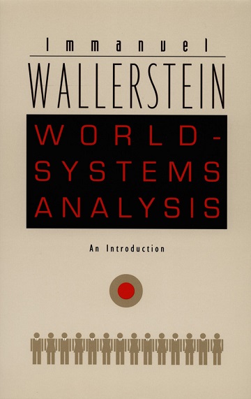
World State Hagger Wallerstein - WorldSystemAnalysis

Negri & Hardt - Empire Frederic Vester - Unsere Welt ein vernetztes System

books


Space Populating - Unite as intergalactic humanity

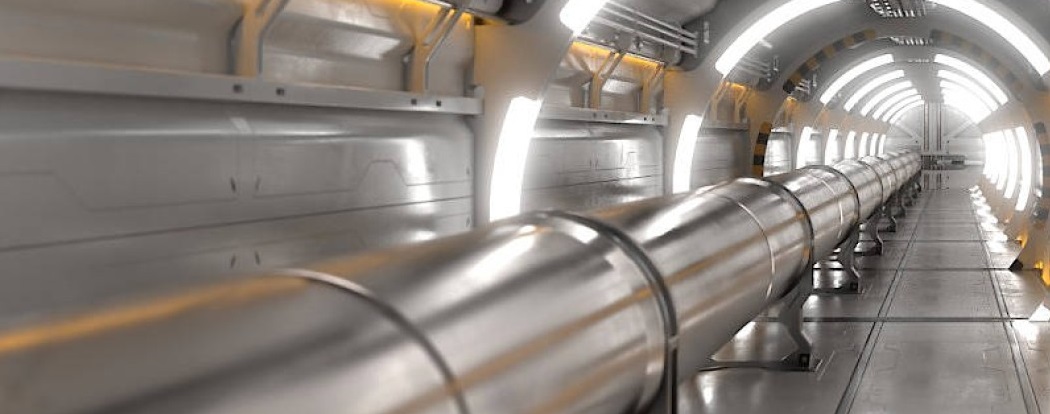
The space Populating project is a system of electromagnetic accelerators which start in the moon; like C.E.R.N. but bigger and straight to shoot us at high velocity into universe.
CERN

electromagnetic accelerator like CERN but bigger and straight for spaceships
EM-Railgun

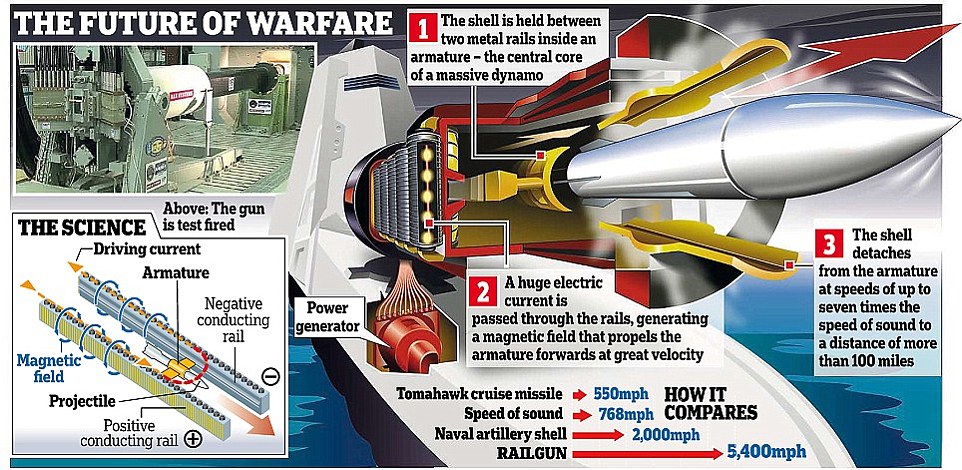
Electromagnetic Railgun

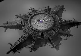
MoonGate

Moon-Gate and Station


An electromagnetic railgun can accelerate a projectile in 5 [meters] to approximatly 10000 [km/h] divided by 3.6 = 2780 [m/s].

v^2 = u^2 + 2as

where a is the acceleration, v is the final velocity, u is the initial velocity, and s is displacement. u = 0

a = v^2 / (2s)

a = 2780^2 [m/s] / (2 * 5 [m])

a ≈ 772 840 m/s^2

Now, we can use the same acceleration to calculate the final velocity of the spaceship on the moon. Since we're given the distance traveled 3 000 000 [m] (diameter moon), we can use the following equation:

v^2 = u^2 + 2as

We're given that the distance traveled is 3,000,000 meters, so:

v = √(2as)

v = √(2 * 772 840 * 3 000 000)

v ≈ 2 153 379 m/s = 7 752 163 [km/h]


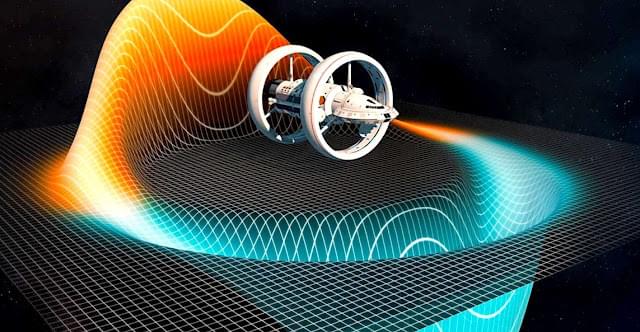
Or scientist discovered a warp-bubble coincidentally!


Warp-Bubble Fanaticalfuturist.com-article

Warp-Bubble epj - european physical journal-article


Alcubierre-Drive

Alcubierre-Drive
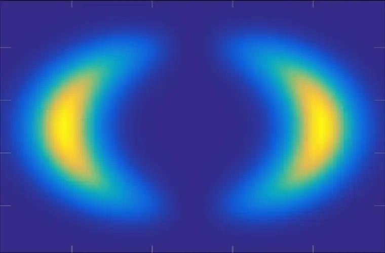
Warp-Bubble

Warp-Bubble


Seafood-Farm

A Seafoodfarm with the surface of state New York could feed the whole world.
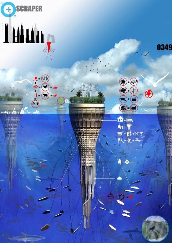
Ocean Bottom Scraper

Ocean Bottom Scraper, gigantic seafood-farm


Dr.Julius Hellenthal offers embryonal stemcelltherapy from umbilical cord tissue in combination with an auto-immune vaccine and longtime AntibioticsTherapy with success against many diseases or strong relief of symptoms.

https://curismo.info

multiple Sclerosis, Epilepsy, Borreliosis (Lyme disease) Alzheimer’s disease, Chrone’s disease, heart attack, cerebral palsy, asthma, all rheumatoid diseases, diseases caused by bacteria, senile maculopathie, retinal detachments, lupus erythematodes, impotency, all different kinds of paralyses, particularly those after accidents, herpetic diseases, for instance herpes of the lips or in the genital tract, tinnitus, all kind of tumors, particularly of the lung, stomach, prostate, skin (particularly: malignant melanoma with nearly 100% success rate after appropriate treatment) tumors of the lips, of the tongue, loss of hair, heart arrhythmia, panic attacks, intelligence improvements in school children, autism, ailments due to diabetes, diabetic retinopathy, Parkinson’s disease and many, many more.

Curismo Youtube

DrJuliusHellenthal


carbonengineering.com

The company invented a process to produce a granulate from the carbon dioxide in the air and use it as fuel.


One facility absorbs as much CO2 as 40 million trees; every gasstation gets a facility to produce the fuel on site.
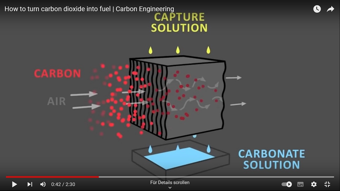
CO2-GranulateFuel

Carbon-Engineering


Syntetic Fuel Wikipedia


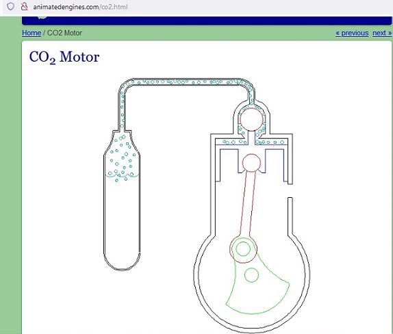
CO2-Engine

CO2-Engine


BoylesFlaskAdvanced (patent application: denied)

BoylesFlaskAdvanced

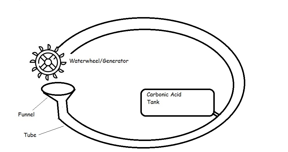
Robert Boyle's Flask works with beer until the carbonic acid disappears. The video on youtube.com is called: “Boyle’s flask works now”. By adding a water wheel as a generator and a sparger for infiltrating carbon dioxide or gas bubbles or a carbonic acid tank the cycle is maintained to win energy.
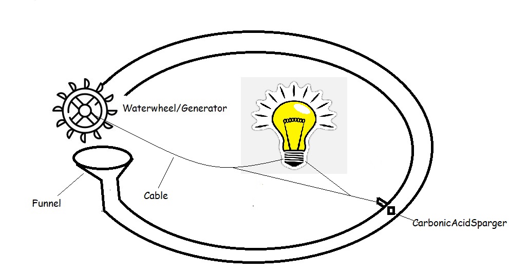
BoylesFlaskPerpetual
BoylesFlaskPerpetual


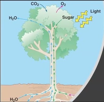
Trees

BiomechanicsTree

BiomechanicsTree


Capillary

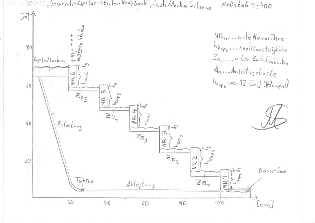
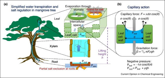
Based on the fact that the Sequoyah/Mammoth trees transport water over 100 meters with the Capillary effect it should be possible to use this to generate energy by immitating the trees or with a mechanism that diverts water at a higher level without any energy input. All of my patent applications were rejected because they were argued to be inoperable or because they were not inventive enough. I hope that someone has a follow-up idea that works... .

SequoyahCapillaryPowerplant
SequoyahCapillaryPowerplant


SequoyahCapillaryStepPowerplant
SequoyahCapillaryStepPowerplant


ProspectsOfArtificialTreeForSolarDesalination

ProspectsOfArtificialTreeForSolarDesalination

ProspectsOfArtificialTreeForSolarDesalination-ScienceDirect

The PatentMagazinePublication: Revolutionizing Water Purification: The Future of Solar Desalination Through Artificial Trees


Passive water ascent in a tall, scalable synthetic tree - Nature Magazine


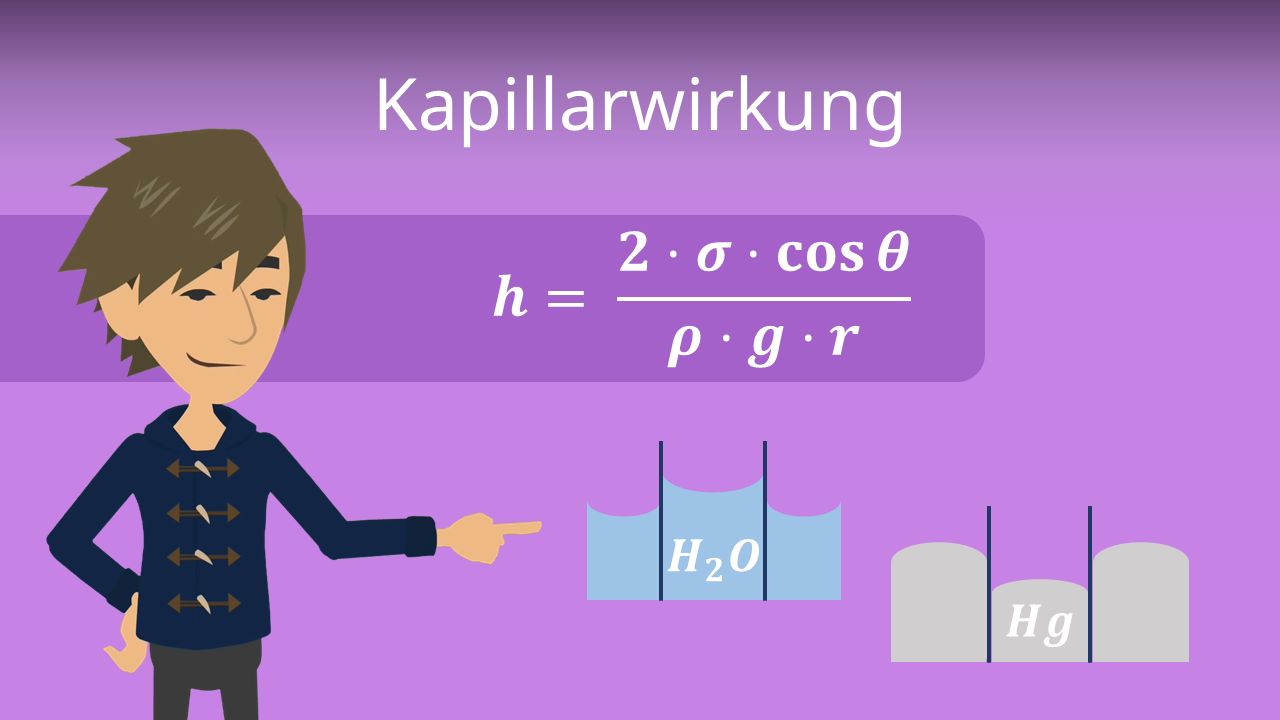
CapillaryFormula


CapillaryFormulaClimbingHight

h = climbing height; σ = surface tension; θ = contact angle; ϱ = density; g = acceleration of gravity; r = radius.
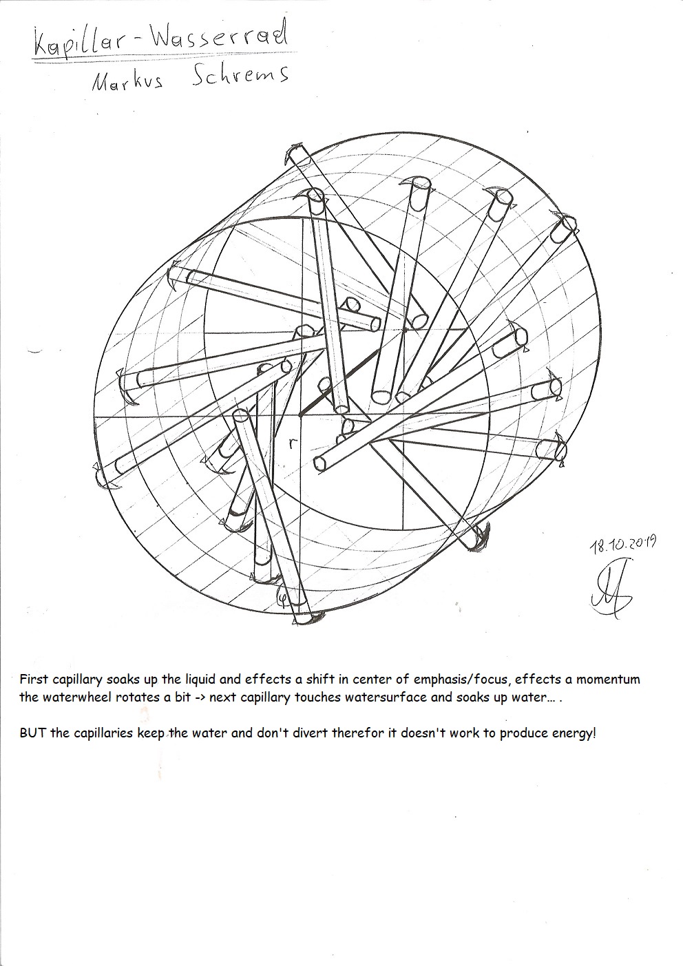

Capillary Waterwheel
Capillary Waterwheel


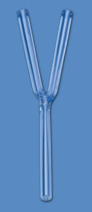
YCapillary

YCapillary fills untill both upper ends
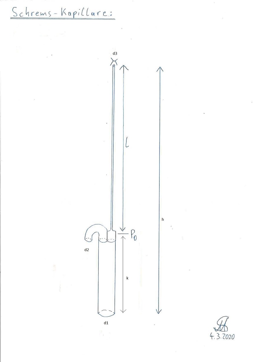

SchremsCapillary (patent application: denied) Schrems-Capillary

Schrems-Capillary: should fill itself completely, but a prototype with measures: k = 3cm; L = 1m; d1 = 0,8mm; d2 = 0,4mm; d3 = 0,02mm didn't work. It filled itself but the pressure at d2 was too low so it didn't divert there.
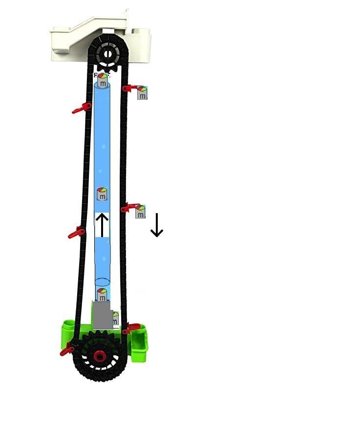

UpliftLift (patent application: denied)

UpliftLift

Masses lighter than water are infiltrated into the water column and move through it because of the hydrostatic uplift upwards. At the upper end the masses are lifted away by the lift and mounted on the lift, they fall downwards to keep the lift moving to generate energy. The uplift lift can also be operated with oil instead of the masses and do the infiltration with a nozzle.


Valve Capillary (Patent application: denied)


ValveCapillary

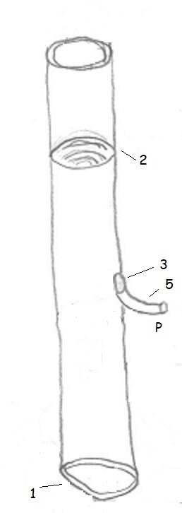
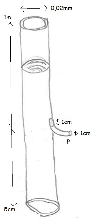
The valve capillary (1) sucks the liquid according to the capillary effect of the diameter of the Capillary-dependent rise height (2) whereby the valve/membrane (3) is closed. The valve/membrane must be designed in such a way that it bridges the capillary effect otherwise a capillary only fills up to a height despite the riser being greater than the length of the pipe below the top opening or a side opening. Then the the valve/membrane opens (3) to divert the liquid at a higher level by the outlet(5) at gravity pressure P. Then it closes the valve/membrane (3) and new liquid is sucked up by the capillary effect... .
ValveCapillary.pdf

ValveCapillaryMesures

A CapillaryCompany produces the Valve-/MembraneCapillary for me... the membrane has a flow threshold pressure of 0,08 Bar. It is more complicated: first I have to find a Company that produces the Membrane, then another company for the capillary (easy) and another one to put the parts together. To make a 1cm hole in a 0,02mm inner diameter capillary to build in the membrane is very hard...seems not any company can produce it .
WettingCapillary (patent application: denied)

WettingCapillary WettingCapillaryHand

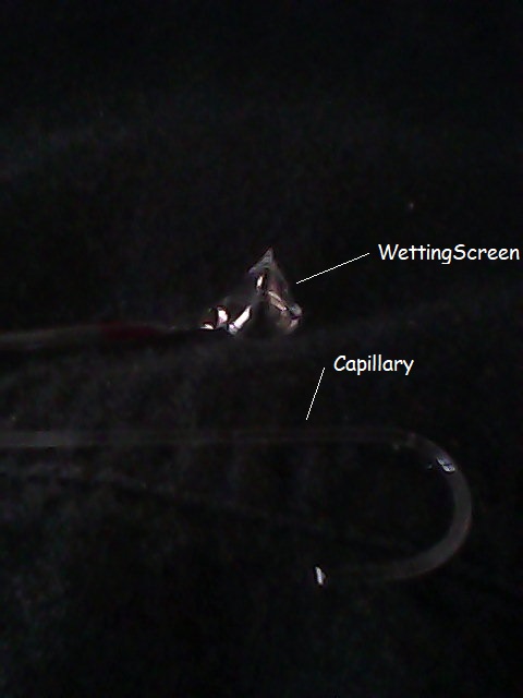
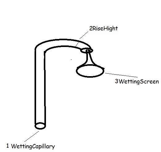
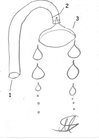
The wetting capillary (1) sucks up the water up to the rise height h (2), which depends on the diameter, and is curved downwards in the upper area. The wetting screen (3) is thinner at the tip than the capillary and the contact angle is very small, which means that the liquid spills over and drips off at the bottom of the screen on a higher level. With surface treatment the wetting of the screen can be raised for example with plasma and other methods.

A glasblowing company produces the capillary and the wettingscreen for me... .
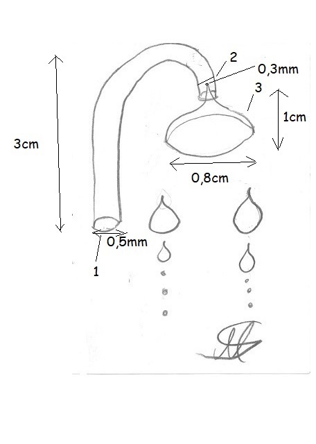
BenetzungsKapillareGlasbläserei WettingCapillaryScreenExperiment

The glasblowing company didn't produce it right. The capillaries are well done but the WettingScreen is too big, it doesn't fit in the capillary and it wasn't open at the upper ending. I tried to mix the experiment with the papertowel but still it doesn't drop off/divert. Professional physicists should do this! Professionals could make it work.

If you now use the wetting capillary with the method from the video: "Capillary action in plants experiment with papertowel" combined, it is logical that the capillary can be diverted at a higher level with papertowel through wetting, capillary-effect and gravity against the hold-back-force of the capillary because the transition of water from one glass to another is more difficult than that.

F_WettingPaperTowel + F_CapillaryPaperTowel + F_Gravity > F_CapillaryHoldBack

WettingCapillaryPublication.pdf

WettingCapillaryExperiment.jpg

Wetting capillary experiment: I bought glass tubes which I heated over a flame and drew from the capillary, it was difficult and it took me many tries. At first the paper towel reached below the waterlevel of the glass and it dripped. When I shortened the paper towel to above the water level, the capillary filled, the paper towel has completely wetted but has not dripped. Almost succes! Professors can make this run!


Investigations into the condition of tensile water in trees.pdf

Plants do also grow in the shadow or in the darkness so the transpiration and negative pressure cannot be the only force why they can supply the leaves with water! The trees have a secret which we should solve.


Patenterstanmeldung

FirstPatentAnouncement

My patent applications are in the direction of perpetual motion and conscious I keep quiet about the production of energy or electricity because otherwise 100% rejection occurs. However, based on my conviction, I am of the opinion that CarnotCycle, energy conservation laws and the proof of the impossibility of a Perpetuum mobiles, i.e. efficiency less than or equal to 1 ONLY for thermodynamic machines applies like motors and there is a loophole.

Wikipedia CarnotCycle

Conservation of energy wikipedia


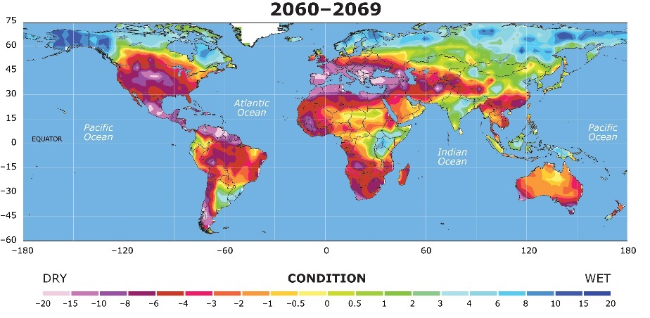
Desertification

Desertification

Desertification


Spock Spock


GreatGreenWallInitiative


ChinaGreatGreenWall

GreenWallOfChina


Acceleration to high velocity

To accelerate a human at 6G to half the speed of light 29 days or 2527232 seconds of acceleration are necessary.

t = (c/2)/a = (149896229[m/s]) / 59[m/s^2] = 2527232 seconds

The total energy required to accelerate a 1000 kg spaceship to half the speed of light at 6G is approximately:

W = F * d

F = 1000 [kg] * 59.28 [m/s^2]

F = 59280 [N]

d = (1/2) * a * t^2

d = (1/2) * 59 [m/s^2] * (2527232 [s])^2

d = 2 * 10^14 [meters]

W = F * d

W = 59280 [N] * 2 * 10^14 [m]

W = 1*10^19 [joules]

To determine the amount of energy that a single Tokamak ITER reactor can produce in 29 days, we need to convert 29 days to seconds, which is 2527232 seconds. The energy produced by a single Tokamak ITER reactor with a power output of 1.5 GW in 29 days is:

energy = power * time

energy = 1.5 [GW] * 2527232 [seconds]

energy = 4 * 10^15 [joules]

W / energy = 1*10^19 [joules] / (4 * 10^15 [joules]) = 2500

Therefore, it would require approximately 2500 Tokamak ITER reactors, each producing 1.5 GW of power, running continuously for 29 days to generate the energy required to accelerate a 1000 kg spaceship to half the speed of light at 6G.

or

E_kinetic = (1/2)*m*v²

E_kinetic = (1/2) * 1000 [kg] * (149896229 [m/s])^2

E_kinetic = 1 * 10^19 [joules]

...


Levitation (patent application)

Why jumps a Popcorn-Pot?

ImpulsRoof > ImpulsFloor + AccelerationRecoil
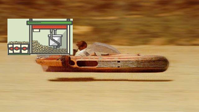
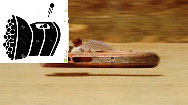
PopcornmashineLandspeeder

PopcornMashineLandspeeder


TennisballmashineLandspeeder

TennisballMashineLandspeeder


Shoot iron balls diagonally up to the ceiling of the chamber so that the falling balls can be reused.

I use electromagnetic acceleration with the balls in the center of a ring-shaped electromagnetic accelerator, that is, in the center of a hollow cylinder or a coil to have little or no recoil.

Never with a railgun, the recoil is too big.


Conservation of momentum:

m_1*v_1 + m_2*v_2 = m_1*v_1' + m_2*v_2'


Q is flow (Q = V/t; in m³/s)

ρ is the density (kg/m³)

V is the volume (in m³)

m is the mass (in kg)

v is velocity (in m/s))

g is acceleration due to gravity (9.8 m/s2)

t is Time (in seconds)

Impuls: p = m*v

Force: F = m*dv/dt = m*a


But the formula must describe a circulating mass-flow and be something like:

F_g = (Δv*m)/dt = (Δv*V*ρ)/dt = Δv*Q*ρ = Δv*Q*γ/g = Δv*ṁ

Δv is velocety-difference between impulse roof and impulse floor

γ specific weight in N/m³ = kg/(m²s²)
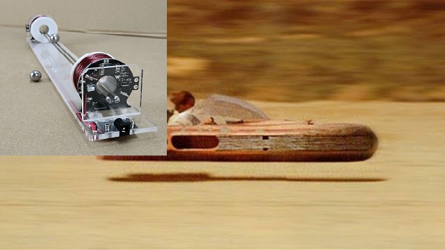

BallElectromagneticAccelerationLandspeeder
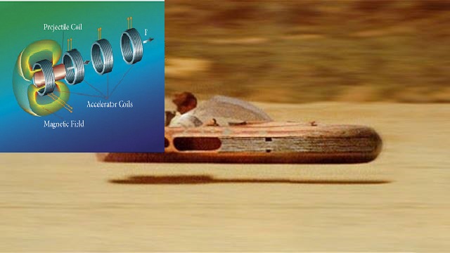
BallElectromagneticAccelerationLandspeeder


ElectromagneticAcceleratorLandspeeder

ElectromagneticAcceleratorLandspeeder


A motor generates the energy for the electromagnetic acceleration. Several such iron-ball-electromagnetic-accelerator-chambers are combined to make a load such as a skateboard or a car levitate or fly.
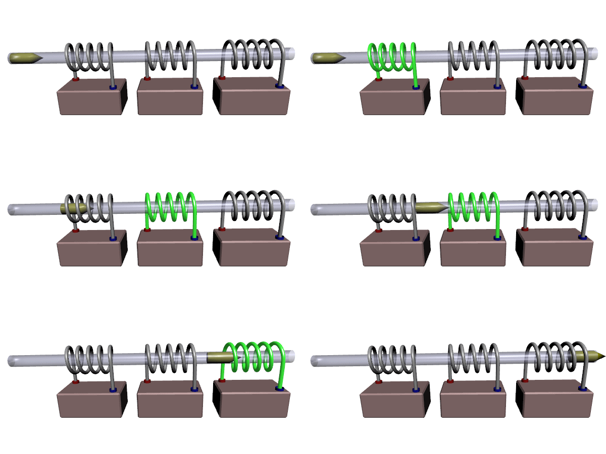

Coilgun

coil gun

v_end = ((2*V* μ_0*χ_m*n²*I²)/m)^1/2

m is mass of the projectile

V is volume projectile

χ_m is magnetic susceptibility

μ_0 is vacuum permeability 4π × 10−7 V*s/(A*m)

I is current in amperes

n is the number of coil turns per unit length of coil obtained by dividing the Total turns of the coil can be determined by the total length of the coil in meters


Force Coilgun:

F = (0.5 * B^2 * A * n * l * I^2) / d

B is the magnetic field strength inside the coilgun (Tesla)

A is the cross-sectional area of the coil (square meters)

n is the number of turns in the coil

l is the length of the coil (meters)

I is the current passing through the coil (Amperes)

d is the distance over which the force is applied (meters)


Quantumfield-Fluctuation-Turbine (patent application: denied)


Physicists Use Quantum Mechanics to Pull Energy out of Nothing - quantamagazine.org
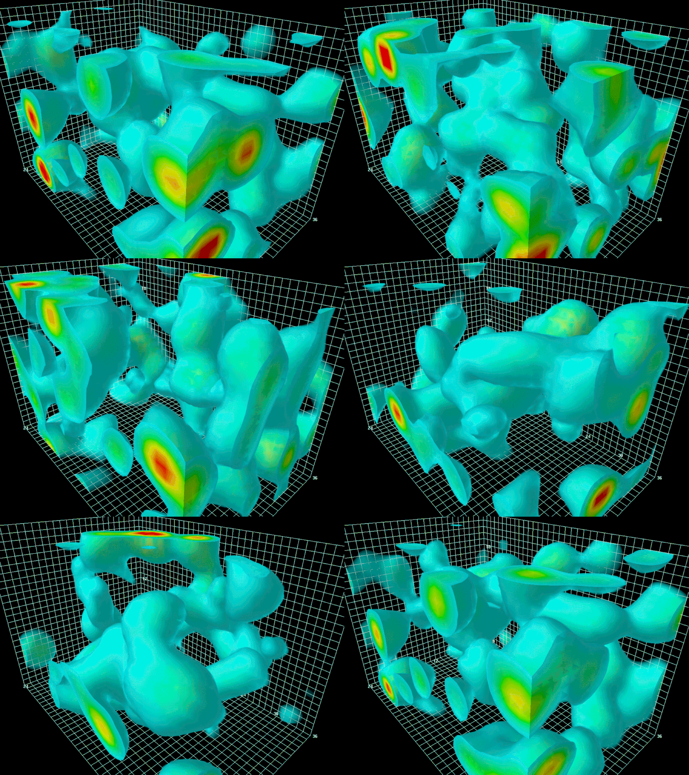

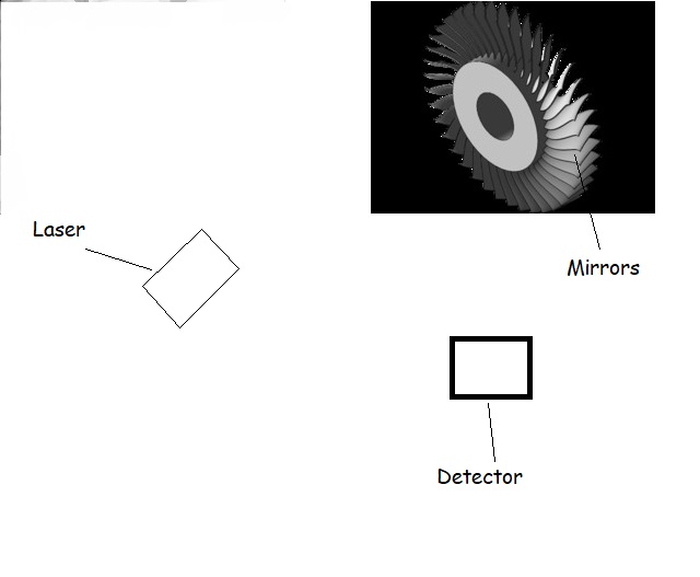
QuantumFluctuations BrownSlowElephant-max-1mbTurbine
Quantumfield-Fluctuations-Turbine QuantumfieldFluctuationsTurbine2

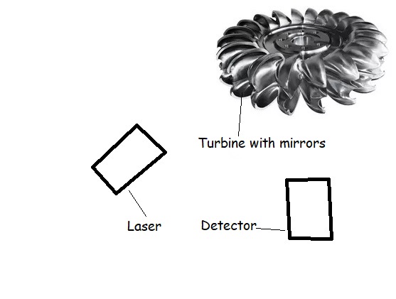
I use 200kW lasers, detectors and silicium-mirrors which are static and completely reflecting instead of the turbine-leaves and it will rotate because of the quantum-fluctuations, quantum noise and the radiation pressure.

QuantumfieldFluctuationsTurbinePatentLawyer.pdf


Quantum fluctuations can jiggle objects on the human scale - M.I.T. LIGO Laboratory

Quantum fluctuations can jiggle objects on the human scale.pdf

M.I.T. LIGO Laboratory nature magazine publication
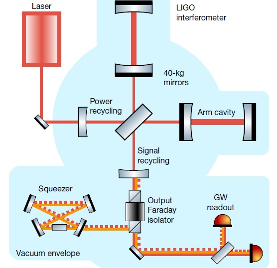

LigoVersuchsaufbau

The radiation pressure

p_st or light pressure is the pressure exerted on a surface by absorbed, emitted or reflected electromagnetic radiation. For absorption and emission, the radiation pressure is equal to the intensity I of the wave divided by the speed of light c: p_st = I/c with the units p_st = N/m² = J/m³ = Pa (Pascal); In the case of complete reflection, the radiation pressure is twice as great as in the case of complete absorption. A photon of frequency ν transports the energy: E = h * ν (see Photoelectric Effect) with the Planck constant h.

Because of the energy-momentum relation E = (p²*c² + m²*c4)^1/2 for the photon with a mass m = 0 follows a momentum p with the magnitude: | p | = h*ν /c

Wave model: The pressure exerted on a surface by a radiation field in a vacuum can be expressed by the Maxwell's stress tensor ( T i j ). With an absorbing surface Normal vector n is the radiation pressure given by: p_st*nj = ∑ Tij* ni The components of Maxwell's stress tensor can be derived from the electrical Calculate the field strength E and the magnetic flux density B:

Tij = (1/ 2)*( ε_0*E² + B²/ μ_0 )*δij − ε_0*Ei*Ej − Bi*Bj/ μ_0

where δij is the Kronecker delta, ε_0 the electric field constant and μ_0 the magnetic field constant is.


Quantum Noise

arises from the quantization of electromagnetic radiation and has a spectral power density of hf. For wavelengths ≤ 10 μm, thermal noise predominates. Optical receivers in the visible range therefore require significantly higher signal power than in the range of electronic frequencies. This occurs when atoms or subatomic particles (electrons, photons or even smaller particles) are involved in an energetic level transition (“quantum jump”). Corresponding measured values ​​(and thus calculation results) are subject to a Probability distribution and are mathematically-probabilistically correct, in the computational practice but often unsatisfactory to unusable.

There is as yet no formulation of the force exerted by quantum fluctuations

QuantumMechanics.pdf


QuantumMechanics2.pdf


ZeroPointEnergy Wikipedia


ZeroPointEnergyGenerator (Patent Application)

TorusDynamo1

A speculative technical diagram showing a device designed to harness Zero-Point Energy

1. Quantum Vacuum Chamber: • Shape: A cylindrical or spherical object that represents the central part of the generator. • Sizing: For example 1 meter diameter for a spherical chamber. • Material: Choose a solid material such as metal or a hypothetical material suitable for vacuum printing. • Position: Place centrally throughout the assembly. Caption: Quantum Vacuum Chamber – captures vacuum energy fluctuations.

2. Electromagnetic Coils: • Shape: Multiple annular or cylindrical coils around the vacuum chamber. • Sizing: Each coil ring could have a smaller diameter than the chamber, for example 0.8 meters. • Material: Copper or similar conductive material. • Quantity: Draw several layers of coils wrapped around the chamber. Caption: High-Frequency Electromagnetic Coils – amplify quantum energy fluctuations.

3. Energy Collectors and Converters: • Shape: Small rectangular plates or cylinders placed along the coils. • Function: They collect the energy amplified by the coils and convert it into electricity. • Position: Draw them at strategic locations along the coils, perhaps at the nodes or connections of the coils. Caption: Energy Collectors – convert amplified fluctuations into electricity.

4. Cooling System: • Shape: Cooling fins or tubes fitted around the generator, particularly around the electromagnetic coils. • Function: Keeps the system at a low temperature to ensure maximum efficiency. • Sizing: Draw along the outer frame of the assembly, perhaps as a network of hoses or cooling fins. Label: Cooling System – maintains low temperatures for optimal efficiency.

5. Supercapacitor Array: • Shape: Several rectangular or cylindrical modules responsible for energy storage. • Sizing: Place them in a row or array to the side of the vacuum chamber. • Location: Directly next to or below the main system, connected to the energy collectors. Caption: Supercapacitors – store collected energy.

6. Power Output Terminals: • Shape: Smaller cylindrical or rectangular ports located on the outside of the system. • Function: Provide the connection for external power delivery. • Position: At the bottom or side of the device.

TorusDynamo1

A conceptual CAD design of a zero-point energy generator. The design includes labeled components such as a vacuum chamber, quantum field coils, energy

1. Vacuum chamber • Description: A hermetically sealed room in which a near-perfect vacuum is created. • Function: Shields external particles and energy sources to create an optimal environment for extraction of zero-point energy. This chamber minimizes outside interference, thereby reducing the Zero point fluctuations in the vacuum can be used more effectively.

2. Quantum field coils • Description: Highly sensitive coils arranged in a special pattern. • Function: These coils interact with the fluctuating quantum fields in the vacuum. They are designed to extract the energy from these fluctuations and convert it into usable convert electrical energy.

3. Energy extraction plates • Description: Flat, conductive plates arranged near the quantum field coils. • Function: They collect and direct the energy generated by the quantum field coils the generator's energy management system. These plates are crucial for efficient Transfer of energy.

4. Control circuits • Description: A network of high-performance circuits and microprocessors. • Function: These circuits monitor and control energy extraction. You adjust the parameters of the Quantum field coils dynamically adjust to maximize energy production and keep the generator stable. They also ensure that the energy generated is routed safely and evenly to the output system becomes.

5. Energieausgangsschnittstelle • Beschreibung: Eine Anschlussvorrichtung, die mit den Energieextraktionsplatten verbunden ist. • Funktion: Sie ermöglicht die Abnahme der erzeugten elektrischen Energie. Die Schnittstelle ist standardisiert, um die Integration in verschiedene Stromnetze und Energiespeichersysteme zu ermöglichen. Sie enthält auch Sicherheitselemente, um Überspannung oder Kurzschluss zu verhindern.

6. Stabilisierungsmodul • Beschreibung: Ein separater Bereich im Generator, der mit fortschrittlicher Elektronik ausgestattet ist. • Funktion: Es reguliert die Energieflüsse innerhalb des Generators, um Schwankungen auszugleichen und eine gleichmäßige Energieabgabe zu gewährleisten. Das Modul verhindert Resonanzphänomene und schützt vor möglichen instabilen Zuständen des Quantenfelds.

7. Kühl- und Isolationssystem • Beschreibung: Ein integriertes System, das aus Kühlrippen, Ventilatoren oder einem Flüssigkeitskühlsystem besteht. • Funktion: Hält die Temperatur des Generators innerhalb optimaler Betriebsbereiche, um eine effiziente Funktion zu gewährleisten. Es schützt empfindliche Komponenten vor Überhitzung und reduziert Energieverluste durch Wärmeabstrahlung.

Funktionsweise des Generators Der Zero-Point-Energy-Generator arbeitet, indem er die Quantenfluktuationen im Vakuum nutzt. Die Quantenfeldspulen erzeugen durch ihre spezielle Anordnung ein Feld, das mit diesen Fluktuationen interagiert und Energie extrahiert. Diese Energie wird über die Energieextraktionsplatten gesammelt und durch die Kontrollschaltkreise stabilisiert. Anschließend wird die Energie an die Energieausgangsschnittstelle weitergeleitet, von wo sie für praktische Anwendungen nutzbar gemacht wird.

TorusDynamo1

A detailed drawing of a quantum field coil with labeled components. The design includes parts like a superconducting coil, magnetic flux stabilizers

1. Superconducting coil • Description: A winding system made of superconducting material that has extremely low resistance. • Function: Generates a strong magnetic field necessary for interaction with quantum fluctuations is. Thanks to superconductivity, the coil can carry high currents without loss of energy, which is crucial for the efficient use of quantum phenomena.

2. Magnetic flux stabilizers • Description: A system of magnets or ferromagnetic materials arranged around the superconducting coil. • Function: Stabilizes the generated magnetic field and controls the flow direction. This creates a creates a uniform and controlled field that effectively focuses the quantum fluctuations and the Energy extraction optimized.

3. Quantum resonance chamber • Description: A cavity surrounding the superconducting coil and made of highly reflective material. • Function: Amplifies the quantum fluctuations in the area of ​​the coil by causing them to resonate with the natural ones Vacuum fluctuations occur. The resonance chamber focuses the energy onto the coil, increasing efficiency energy production is increased.

4. Control circuit interface • Description: An electronic circuit connected to the coil and stabilizers. • Function: Monitors and regulates the operating parameters of the quantum field coil. It adjusts the current flow and the magnetic fields to optimize the resonance conditions and maximize energy yield achieve. The interface also allows adaptation to different operating modes and conditions.

5. Energy output terminals • Description: Electrical connections connected to the coil. • Function: Transfer the energy gained from the coil to the external energy system. These terminals are designed to transmit the energy gained with minimal loss and at the same time protect against possible feedback effects.

6. Cooling and insulation system • Description: A system of cooling fins or liquid cooling tubes arranged around the superconducting coil and the quantum resonance chamber. • Function: Keeps the superconducting coil at a low temperature to maintain the superconducting state to maintain. At the same time, it thermally insulates the system to minimize external heat influences and to ensure the stability of the magnetic field.

7. Vibration damper • Description: Shock-absorbing materials or structures attached to the coil attachment points. • Function: Reduce mechanical vibrations, which affect the stability of the magnetic field and therefore efficiency could affect energy extraction. They ensure that the coil is in an optimal position remains and works undisturbed.

How the quantum field coil works The quantum field coil works by generating a controlled magnetic field that interacts with the vacuum fluctuations. The superconducting coil creates a strong magnetic field, while the magnetic flux stabilizers focus and stabilize this field. In the quantum resonance chamber, the quantum fluctuations are amplified, transferring more energy into the coil. The control circuit interface monitors the conditions within the coil and adjusts the parameters in real time to ensure optimal energy harvesting. The cooling and insulation system keeps the coil at the necessary low temperature to maintain the superconducting state and minimize energy losses. The energy obtained is then transferred via the energy output terminals to an external system, where it can be used for various applications. The vibration dampers ensure that the system remains mechanically stable, thus ensuring the integrity of the magnetic field and energy extraction.

TorusDynamo1

A detailed technical diagram of Nikola Tesla's Wardenclyffe Tower

PulsatingEarthMagneticFieldGenerator (Patent Application)

Adam Trombley Generator (Patent Application)

energetic torus that uses the pulsating magnetic field of earth to produce energy with induction...


TorusDynamo1

TorusDynamo1 Adam Trombly

TorusDynamo2

TorusDynamo2 Adam Trombly


AdamTromblyPulsatingTorus

AdamTromblyPulsatingTorus


AdamTromblyPulsatingTorus

A conceptual CAD drawing of a free energy generator inspired by speculative energy concepts by Adam Trombley


AdamTromblyPulsatingTorus

A speculative diagram of the Adam Trombley generator

1. Rotor with magnets • Description: The rotor is a central, rotating component of the generator. It consists of a cylindrical or disk-shaped body equipped with permanent magnets. These magnets are evenly distributed on the surface of the rotor. • Function: When the rotor rotates, the magnets create a changing magnetic field that leads to induction electrical energy in the coils of the stator.

2. Stator • Description: The stator surrounds the rotor and is equipped with copper coils around an iron core. These coils are often configured as windings that use the rotor's changing magnetic field to generate an electrical voltage. • Function: The stator absorbs the changing magnetic field of the rotating rotor and induces electrical energy Current in the copper coils.

3. Copper coils (induction coils) • Description: Copper coils are coils of copper wire wrapped around the stator. Copper is a common material for such applications due to its high conductivity. • Function: The movement of the rotor creates a magnetic field in the coils, which creates an electrical Allows current to flow through electromagnetic induction.

4. Capacitor bank • Description: The capacitor bank consists of a series of capacitors connected in series or parallel to store the electrical energy generated by the copper coils. • Function: The capacitors temporarily store electrical energy and smooth out voltage fluctuations and provide energy when the generator begins to fluctuate.

5. Frequency converter (frequency converter) • Description: The frequency converter is an electronic component that adjusts the frequency of the alternating voltage generated by the coils. • Function: It converts the electrical energy produced by the generator into a usable frequency, whichever must be adjusted according to application (e.g. 50 Hz or 60 Hz).

6. Flywheel • Description: A flywheel is a solid, often metallic, disk or cylinder attached to the axis of the rotor. • Function: The flywheel stores kinetic energy and ensures that the rotor rotates remains even. It stabilizes the operation of the generator by reducing fluctuations in the Rotation speed reduced.

7. Bearing and axle • Description: The bearings and axle are mechanical components that allow the rotor to rotate with as little friction as possible. • Function: The bearings support rotational movement and minimize mechanical energy loss Friction. They ensure that the rotor can rotate smoothly and stably.

8. Frame structure • Description: The generator frame is the outer casing that holds all of the internal components (rotor, stator, flywheel, bearings, etc.) together. It is often made of aluminum or steel to ensure robustness and stability. • Function: The frame protects the internal components and ensures that the generator is structurally stable remains and mechanical vibrations are minimized.

9. Control electronics • Description: The control electronics is a set of electronic components that monitor and control the operation of the generator. • Function: It regulates the energy flow, monitors the output voltage and current, and ensures that the generator works efficiently, without unstable fluctuations in energy production.

Summary of how it works: The Adam Trombley Generator uses the motion of a rotating magnetic rotor within a stationary one Stator, which is equipped with copper coils. The rotation of the rotor creates the magnets changing magnetic field that induces an electric current in the copper coils. This current is supplied by a Capacitor bank stored and regulated by a frequency converter. A flywheel ensures stability, by storing kinetic energy, and the control electronics monitors the entire functioning of the system.


TorusDynamo3 AdamTrombleyEarthMacneticFieldGenerator (Patent Application)

1. Rotor • Description: The rotor is the heart of the generator and consists of a rotating cylinder or disk. Permanent magnets are attached to the surface of the rotor and are evenly distributed. The rotor itself is mounted in a stable bearing so that it can rotate with as little resistance as possible. • Function: The rotor rotates continuously and ensures that the attached magnets move in relation to the surrounding copper coils. This movement creates a changing magnetic field, which is the prerequisite for the generation of electrical energy through electromagnetic induction. The rotation of the rotor can be caused by external forces such as a motor, but in this case speculatively by interaction with the Earth's magnetic field.

2. Magnets on the rotor • Description: The permanent magnets are firmly attached to the surface of the rotor. These magnets are aligned to project the maximum magnetic field into the area of ​​the coils. • Function: As the rotor rotates, the magnets move past the copper coils. This movement creates a dynamic magnetic field that cuts through the coils and induces a voltage in them. The crucial mechanism is the continuous change in the magnetic field caused by the rotation of the magnets.

3. Coils (copper windings) • Description: The coils consist of many turns of copper wire wound around an iron core or evacuated form. Copper is preferred due to its excellent conductivity and low electrical losses. • Function: The copper coils are where the actual energy generation takes place. As the magnets on the rotor move past the coils, they create a changing magnetic field that cuts through the coils' turns and creates a voltage. This principle is called electromagnetic induction and is the same as that used in conventional generators. The faster the magnets rotate or the stronger the magnetic field, the more voltage is generated in the coils.

4. Capacitor bank • Description: The capacitor bank consists of several capacitors connected in series or parallel to store the electrical energy generated. Capacitors are passive electronic components that can store electrical charge and release it again when necessary. • Function: The capacitor bank plays a key role in stabilizing the power generated. When power generation is irregular - for example due to fluctuations in rotor rotation - capacitors can buffer the energy and deliver it to consumers at a constant voltage and current. They act like a temporary battery that absorbs voltage spikes and keeps the system stable.

5. Bearing • Description: Bearings consist of mechanical components that allow the rotor to rotate with little friction. They are often lubricated or made from materials specifically designed for long life and minimal friction. • Function: The bearings keep the rotor stable and ensure that it can rotate with minimal energy loss. They minimize mechanical friction that could otherwise cause the rotor to slow down or even stop. Ideally, the bearings must be extremely durable and low-maintenance to ensure the smoothest possible rotation.

6. Flywheel • Description: The flywheel is a large, usually heavy disk or cylinder that is attached to the axis of rotation of the rotor. It is often made of metal and has a high mass. • Function: The flywheel stores kinetic energy in the form of rotational motion. Once set in motion, it ensures that the rotor continues to run smoothly, even if there are slight fluctuations in torque. The flywheel helps smooth the energy output and ensures continuous power production by stabilizing the rotation. This is particularly useful when the rotor is subjected to irregular driving forces.

7. Frame structure • Description: The frame structure is the mechanical framework of the generator that holds all components together. It is usually made of a sturdy material such as steel or aluminum and provides space for the rotor, coils, bearings and electronics. • Function: The frame keeps the generator stable and ensures that all components stay securely in place. In addition, the frame protects the generator from external influences such as vibrations or physical shocks. It also minimizes mechanical deformation that could arise from operation and helps dampen vibrations and noise.

8. Earth's magnetic field • Description: The Earth's magnetic field is a natural, invisible magnetic field created by the movement of liquid iron in the Earth's outer core. It permeates the entire planet and varies in strength depending on location. • The drawing shows lines that represent the Earth's magnetic field interacting with the rotor. This natural magnetic field is the source from which energy is derived. • Function: In this speculative theory, the Earth's magnetic field could interact directly with the generator's magnet and rotor. The idea is that by properly aligning and moving the rotor, the Earth's magnetic field can be used to power the generator or provide additional energy. This could theoretically occur through the interaction of the rotor's permanent magnets with the Earth's magnetic field to amplify or modulate the magnetic field and thereby generate additional energy.

9. Control electronics (optional) • Description: The control electronics include components such as voltage regulators, frequency converters and circuits that monitor and control the operation of the generator. • Function: These components regulate the voltage and current that the generator produces and adjust the frequency of the alternating current produced to make it suitable for various applications. The electronics ensure that the energy supply remains stable and that no harmful voltage fluctuations occur.

Working principle of earth magnetic field generator: The generator's rotor is caused to rotate by external forces or by interactions with the earth's magnetic field. The attached magnets create a changing magnetic field that flows through the copper coils on the stator, thereby generating electrical current. This current is stored in the capacitor bank and regulated by the control electronics to provide stable and usable electrical energy. A flywheel helps keep the rotational motion smooth, while the bearings and frame ensure the rotor works smoothly and efficiently. The Earth's magnetic field could theoretically help strengthen or maintain the magnetic field in the generator.


TorusDynamo3

TorusDynamo3


TorusDynamo4

TorusDynamo4


TorusFieldOfPlanetEarth

TorusFieldOfPlanetEarth


EarthMagneticField

EarthMagneticField


EarthMagneticField2

EarthMagneticField2


EarthMagneticField3

EarthMagneticField3


HeartsMagneticField

HeartsMagneticField


HeartsMagneticField

Chat GPT painted a construction plan...

1. Induction coil 2. Magnetic field 3. Energy conversion unit 4. Capacitor bank 5. Connections 6. Grounding 7. Measuring instruments 8. Current meter 9. Voltmeter 10. Capacitor


HeartsMagneticField

Chat GPT blueprint

1. Coil 2. Magnetic field lines 3. Capacitor 4. Connections 5. Grounding 6. Current meter 7. Voltage meter


"MicroPulsations of Earth's magnetic field..."Nature Magazine


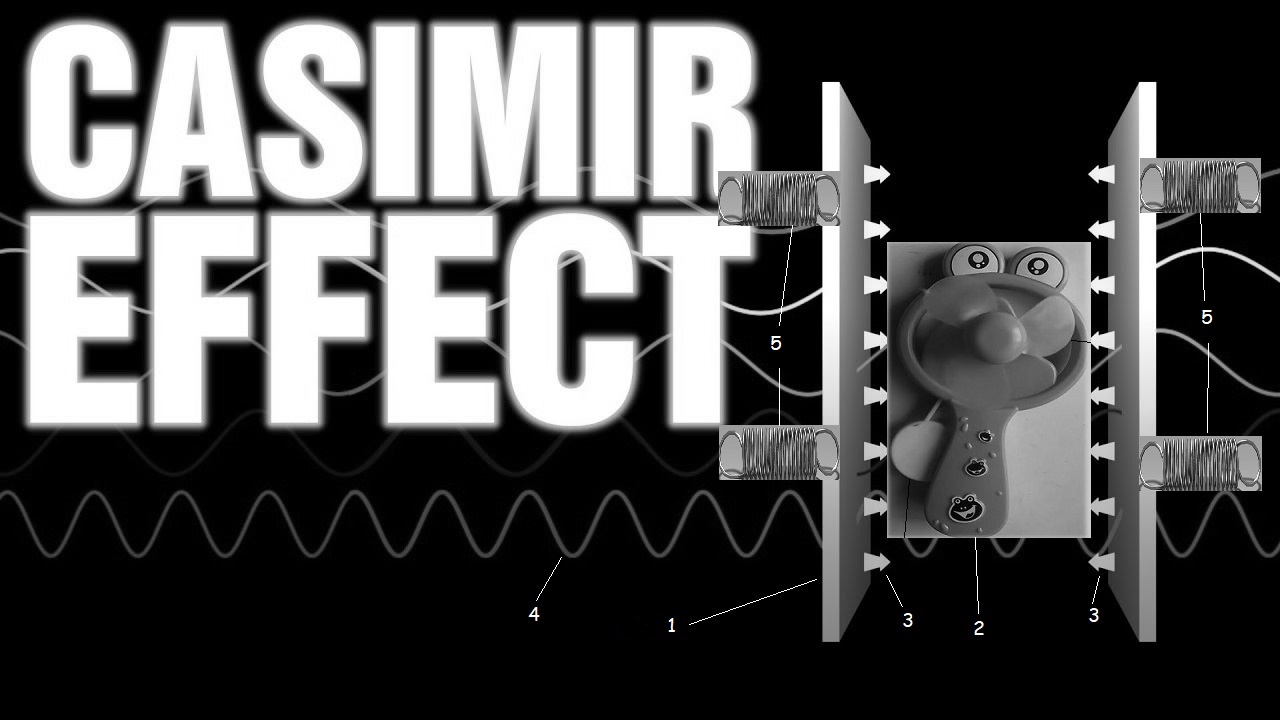
ManualHandFanCasimirEffect (patent application: denied)

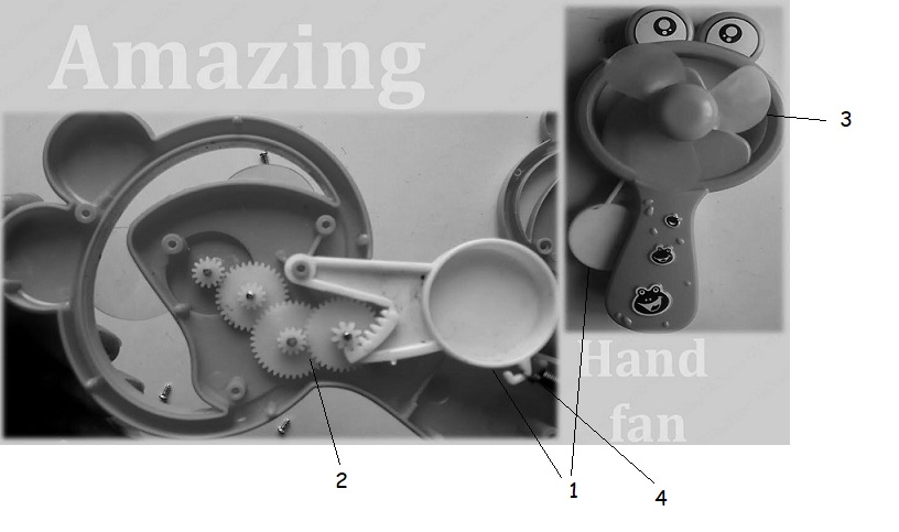
HandFanMechanism

Mechanics of a manual hand fan (3) with return spring (4), drive lever (1) and gear power transmission (2)
HandFanMechanism

consisting of Casimir effect panels (1), manual hand fan (2) with Return springs (5), Casimir force (3) and quantum fields/fluctuations in different wavelengths (4)

The manual hand fan: by repeatedly applying pressure to a lever causes through a gear mechanism generates rotational energy using the Casimir effect and is returned to the starting position of the lever by a spring or rubber ring.


HeadMaze

HeadMaze


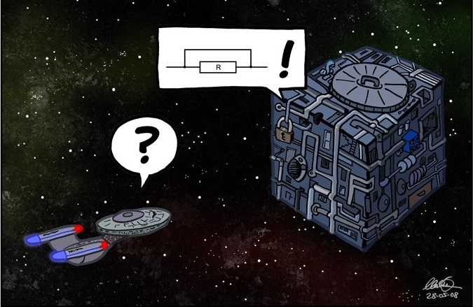
GyroGearloose Gyro Gearloose EnterpriseResistanceIsFutile Enterprise and the Borg


VisitorCounter installed 9.December 2023


e-mail contacts World Representatives/MP's/Diputados/Senators/Abgeordnete Parliaments.pdf

e-mail or facebook contacts World Political Parties.pdf


https://www.youtube.com/@magoam8502/videos


Etsy.com-Shop


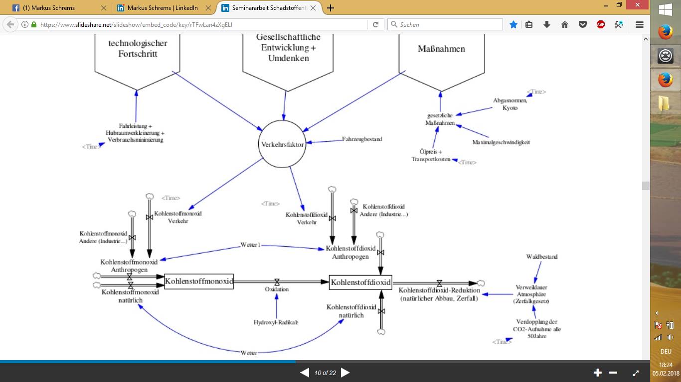
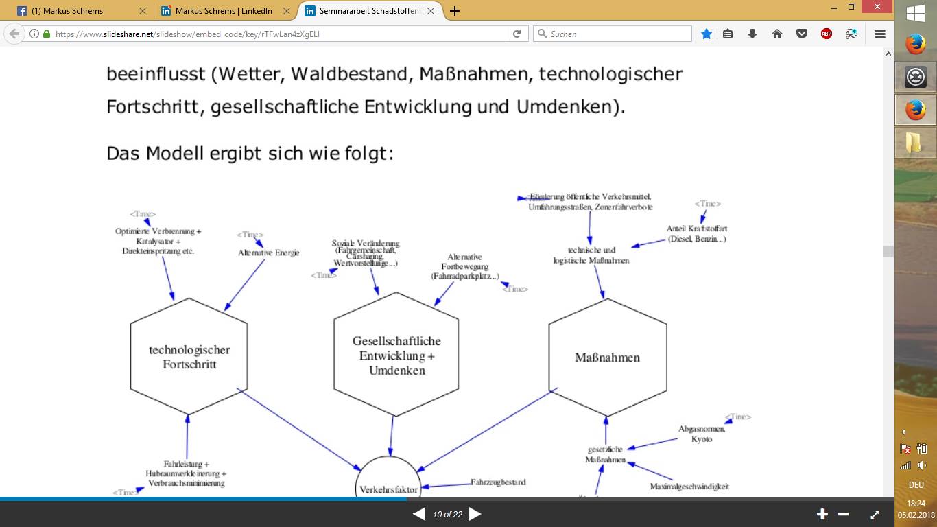
EnvironmentSystemScienceSeminarWorkCO2Cycle

Technological progress (optimized combustion, catalytic converter, direct injection alternative energy, mileage, reduction in displacement, minimization of consumption)

Social development and rethinking (social change, carpooling, Car sharing, value proposition), alternative transport (bicycle parking space))

Measures (technical and logistical measures (promotion of public transport, Bypasses, zone driving bans, proportion of fuel type), legal measures (Kyoto, maximum speed, oil price, transport costs))

Traffic factor (technological progress, social development and rethinking, Measures)

Carbon monoxide (natural, anthropogenic (traffic factor), other (industry, ...))

Carbon dioxide (carbon monoxide(oxidation), natural, anthropogenic)

Carbon dioxide reduction (natural degradation (forest...), decay)
QuantumFluctuations QuantumFluctuations QuantumFluctuations

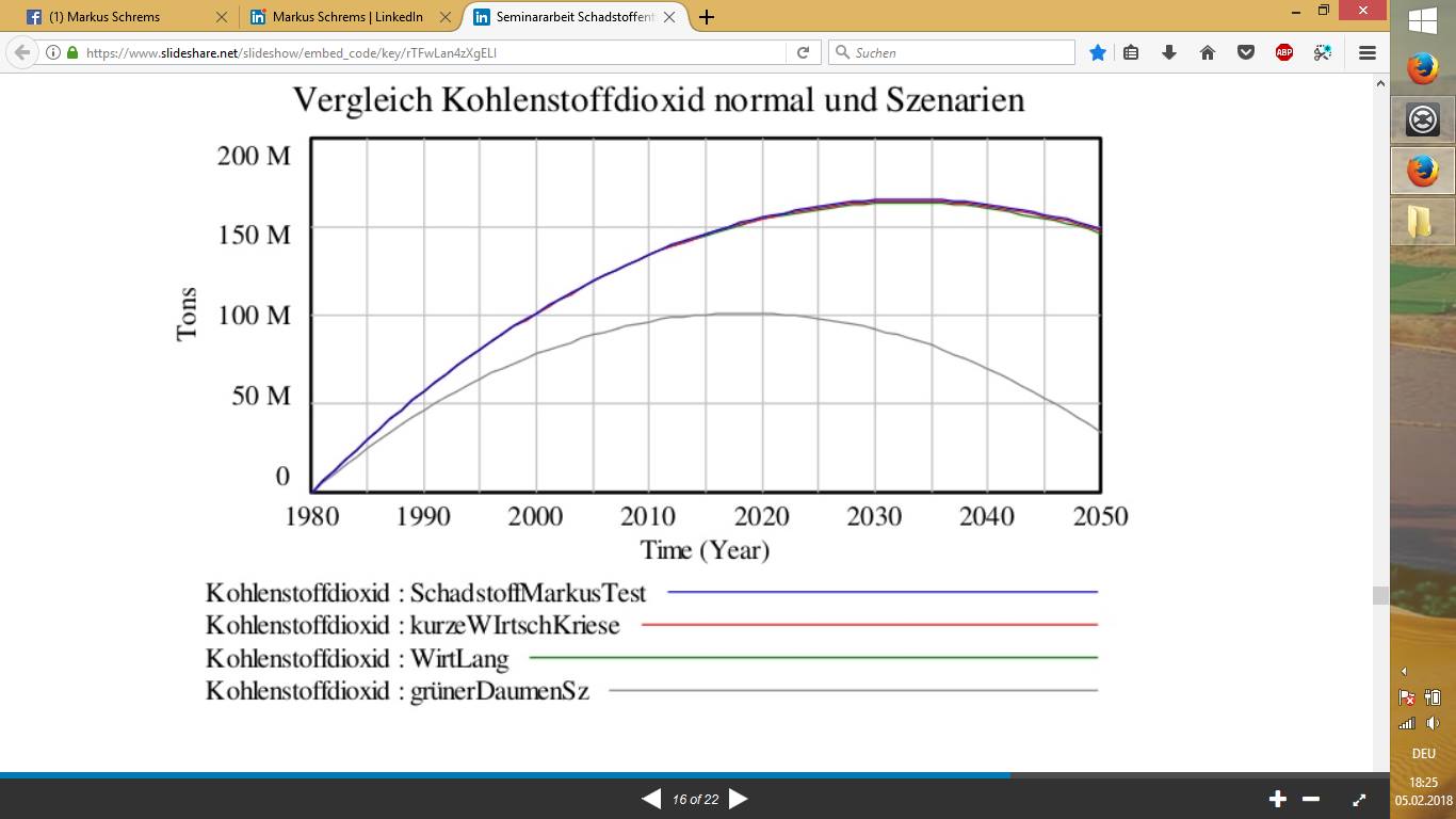
Success in scenario: "grüner Daumen/green thumb (planting trees)"


Plastic eating worms


Sphere n-Dimensional


Volume and Surface n-dimensional spheres


Sphere n-dimensional.pdf


Lyrics:

Ölkonzerne = Oilcompanies

pumpen in der Ferne = pumping in the distance

zerstören unsere Umwelt = destroying our environment

nur für nen Batzen Geld = only for a lot of money

worin wir unsere Zukunft sehn = what we see as our future

erneuerbare Energie = renewable energy


office@worldstate.org

Imprint Privacy Policy