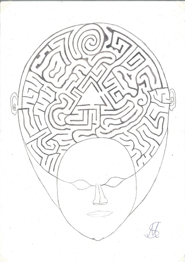
I read a book about shamanism and I don't know if it's true with the lightbody-dimension
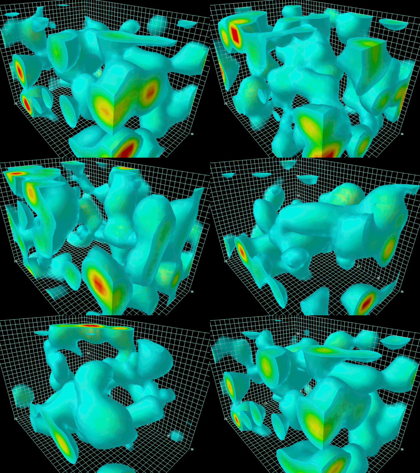
but if I have headace I imagine a big sphere around my body which is deformed by any
impressions/influences. If I make the sphere smooth the headace goes away and the thoughts/brain
seem to bend. Please try it and give me feedback if it is just an illusion or real force!
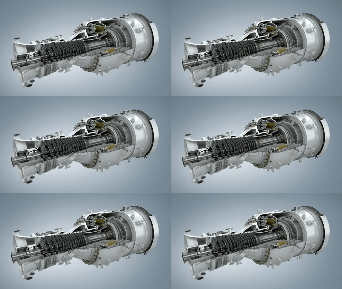
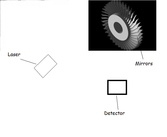
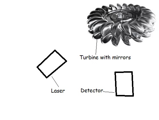
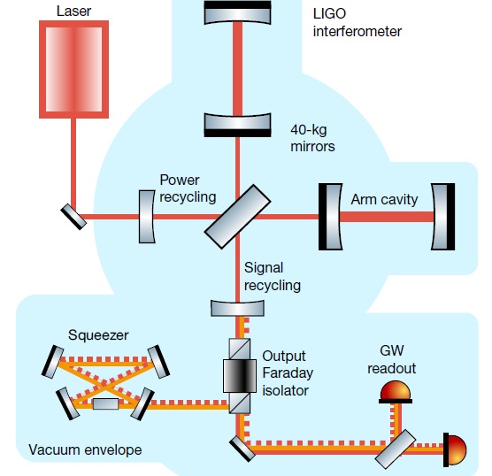
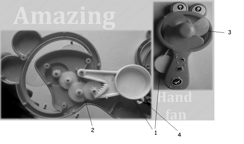
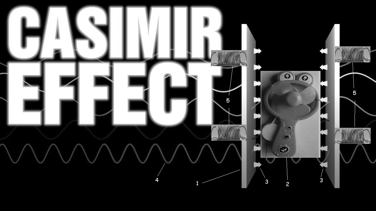
I use 200kW lasers, detectors and silicium-mirrors which are static and completely reflecting instead of the
turbine-leaves and it will rotate
because of the quantum-fluctuations, quantum noise and the radiation pressure.
p_st or light pressure is the pressure exerted on a surface by absorbed, emitted or reflected
electromagnetic radiation.
For absorption and emission, the radiation pressure is equal to the intensity I of the wave
divided by the speed of light c:
p_st = I/c with the units p_st = N/m² = J/m³ = Pa (Pascal);
In the case of complete reflection, the radiation pressure is twice as great as in the case
of complete absorption.
A photon of frequency ν transports the energy:
E = h * ν (see Photoelectric Effect)
with the Planck constant h.
Because of the energy-momentum relation
E = (p²*c² + m²*c4)^1/2
for the photon with a mass m = 0 follows a momentum p with the magnitude:
| p | = h*ν /c
Wave model:
The pressure exerted on a surface by a radiation field in a vacuum can be expressed by the
Maxwell's stress tensor ( T i j ). With an absorbing surface
Normal vector n is the radiation pressure given by:
p_st*nj = ∑ Tij* ni
The components of Maxwell's stress tensor can be derived from the electrical
Calculate the field strength E and the magnetic flux density B:
where δij is the Kronecker delta, ε_0 the electric field constant and μ_0 the
magnetic field constant is.
Quantum Noise
arises from the quantization of electromagnetic radiation and has a spectral
power density of hf. For wavelengths ≤ 10 μm, thermal noise predominates.
Optical receivers in the visible range therefore require significantly higher signal power
than in the range of electronic frequencies.
This occurs when atoms or subatomic particles (electrons, photons or
even smaller particles) are involved in an energetic level transition (“quantum jump”).
Corresponding measured values (and thus calculation results) are subject to a
Probability distribution and are mathematically-probabilistically correct, in the
computational practice but often unsatisfactory to unusable.
There is as yet no formulation of the force exerted by quantum fluctuations
A technical diagram showing a device designed to harness Zero-Point Energy
1. Quantum Vacuum Chamber:
• Shape: A cylindrical or spherical object that represents the central part of the generator.
• Sizing: For example 1 meter diameter for a spherical chamber.
• Material: Choose a solid material such as metal or a hypothetical material suitable for vacuum printing.
• Position: Place centrally throughout the assembly.
Caption: Quantum Vacuum Chamber – captures vacuum energy fluctuations.
2. Electromagnetic Coils:
• Shape: Multiple annular or cylindrical coils around the vacuum chamber.
• Sizing: Each coil ring could have a smaller diameter than the chamber, for example 0.8 meters.
• Material: Copper or similar conductive material.
• Quantity: Draw several layers of coils wrapped around the chamber.
Caption: High-Frequency Electromagnetic Coils – amplify quantum energy fluctuations.
3. Energy Collectors and Converters:
• Shape: Small rectangular plates or cylinders placed along the coils.
• Function: They collect the energy amplified by the coils and convert it into electricity.
• Position: Draw them at strategic locations along the coils, perhaps at the nodes or connections of the coils.
Caption: Energy Collectors – convert amplified fluctuations into electricity.
4. Cooling System:
• Shape: Cooling fins or tubes fitted around the generator, particularly around the electromagnetic coils.
• Function: Keeps the system at a low temperature to ensure maximum efficiency.
• Sizing: Draw along the outer frame of the assembly, perhaps as a network of hoses or cooling fins.
Label: Cooling System – maintains low temperatures for optimal efficiency.
5. Supercapacitor Array:
• Shape: Several rectangular or cylindrical modules responsible for energy storage.
• Sizing: Place them in a row or array to the side of the vacuum chamber.
• Location: Directly next to or below the main system, connected to the energy collectors.
Caption: Supercapacitors – store collected energy.
6. Power Output Terminals:
• Shape: Smaller cylindrical or rectangular ports located on the outside of the system.
• Function: Provide the connection for external power delivery.
• Position: At the bottom or side of the device.
A CAD design of a zero-point energy generator.
1. Vacuum chamber
• Description: A hermetically sealed room in which a near-perfect vacuum is created.
• Function: Shields external particles and energy sources to create an optimal environment for extraction
of zero-point energy. This chamber minimizes outside interference, thereby reducing the
Zero point fluctuations in the vacuum can be used more effectively.
2. Quantum field coils
• Description: Highly sensitive coils arranged in a special pattern.
• Function: These coils interact with the fluctuating quantum fields in the vacuum.
They are designed to extract the energy from these fluctuations and convert it into usable
convert electrical energy.
3. Energy extraction plates
• Description: Flat, conductive plates arranged near the quantum field coils.
• Function: They collect and direct the energy generated by the quantum field coils
the generator's energy management system. These plates are crucial for efficient
Transfer of energy.
4. Control circuits
• Description: A network of high-performance circuits and microprocessors.
• Function: These circuits monitor and control energy extraction. You adjust the parameters of the
Quantum field coils dynamically adjust to maximize energy production and keep the generator stable.
They also ensure that the energy generated is routed safely and evenly to the output system
becomes.
5. Energy output interface
• Description: A connector device connected to the energy extraction plates.
• Function: It enables the electrical energy generated to be consumed. The interface is
standardized to enable integration into various power grids and energy storage systems.
It also contains safety elements to prevent overvoltage or short circuit.
6. Stabilization module
• Description: A separate area in the generator equipped with advanced electronics.
• Function: It regulates the energy flows within the generator to compensate for fluctuations and a
to ensure uniform energy delivery. The module prevents resonance phenomena and protects against possible ones
unstable states of the quantum field.
7. Cooling and insulation system
• Description: An integrated system consisting of cooling fins, fans or a liquid cooling system.
• Function: Maintains the generator temperature within optimal operating ranges to ensure efficient
to ensure function. It protects sensitive components from overheating and reduces energy losses
through heat radiation.
How the generator works
The Zero Point Energy Generator works by exploiting the quantum fluctuations in the vacuum.
Due to their special arrangement, the quantum field coils create a field that corresponds to these fluctuations
interacts and extracts energy. This energy is collected via the energy extraction plates and
stabilized by the control circuits. The energy is then sent to the energy output interface
forwarded, from where it can be used for practical applications.
A detailed drawing of a quantum field coil with labeled components.
1. Superconducting coil
• Description: A winding system made of superconducting material that has extremely low resistance.
• Function: Generates a strong magnetic field necessary for interaction with quantum fluctuations
is. Thanks to superconductivity, the coil can carry high currents without loss of energy, which is crucial for the
efficient use of quantum phenomena.
2. Magnetic flux stabilizers
• Description: A system of magnets or ferromagnetic materials arranged around the superconducting coil.
• Function: Stabilizes the generated magnetic field and controls the flow direction. This creates a
creates a uniform and controlled field that effectively focuses the quantum fluctuations and the
Energy extraction optimized.
3. Quantum resonance chamber
• Description: A cavity surrounding the superconducting coil and made of highly reflective material.
• Function: Amplifies the quantum fluctuations in the area of the coil by causing them to resonate with the natural ones
Vacuum fluctuations occur. The resonance chamber focuses the energy onto the coil, increasing efficiency
energy production is increased.
4. Control circuit interface
• Description: An electronic circuit connected to the coil and stabilizers.
• Function: Monitors and regulates the operating parameters of the quantum field coil. It adjusts the current flow
and the magnetic fields to optimize the resonance conditions and maximize energy yield
achieve. The interface also allows adaptation to different operating modes and conditions.
5. Energy output terminals
• Description: Electrical connections connected to the coil.
• Function: Transfer the energy gained from the coil to the external energy system. These terminals
are designed to transmit the energy gained with minimal loss and at the same time
protect against possible feedback effects.
6. Cooling and insulation system
• Description: A system of cooling fins or liquid cooling tubes arranged around the superconducting coil and the quantum resonance chamber.
• Function: Keeps the superconducting coil at a low temperature to maintain the superconducting state
to maintain. At the same time, it thermally insulates the system to minimize external heat influences
and to ensure the stability of the magnetic field.
7. Vibration damper
• Description: Shock-absorbing materials or structures attached to the coil attachment points.
• Function: Reduce mechanical vibrations, which affect the stability of the magnetic field and therefore efficiency
could affect energy extraction. They ensure that the coil is in an optimal position
remains and works undisturbed.
How the quantum field coil works
The quantum field coil works by generating a controlled magnetic field that interacts with the vacuum fluctuations. The superconducting coil creates a strong magnetic field, while the magnetic flux stabilizers focus and stabilize this field. In the quantum resonance chamber, the quantum fluctuations are amplified, transferring more energy into the coil.
The control circuit interface monitors the conditions within the coil and adjusts the parameters in real time to ensure optimal energy harvesting. The cooling and insulation system keeps the coil at the necessary low temperature to maintain the superconducting state and minimize energy losses.
The energy obtained is then transferred via the energy output terminals to an external system, where it can be used for various applications. The vibration dampers ensure that the system remains mechanically stable, thus ensuring the integrity of the magnetic field and energy extraction.
A detailed technical diagram of Nikola Tesla's Wardenclyffe Tower
A generator designed to harness energy from the pulsating Earth's magnetic field
1. Induction coil
2. Magnetic field
3. Energy conversion unit
4. Capacitor bank
5. Connections
6. Grounding
7. Measuring instruments
8. Current meter
9. Voltmeter
10. Capacitor
A generator designed to harness energy from the pulsating Earth's magnetic field
1. Coil
2. Magnetic field lines
3. Capacitor
4. Connections
5. Grounding
6. Current meter
7. Voltage meter
energetic torus that uses the pulsating magnetic field of earth to produce energy with induction...
Adam Trombley Generator
Diagram of the Adam Trombley generator
1. Rotor with magnets
• Description: The rotor is a central, rotating component of the generator. It consists of a cylindrical or disk-shaped body equipped with permanent magnets. These magnets are evenly distributed on the surface of the rotor.
• Function: When the rotor rotates, the magnets create a changing magnetic field that leads to induction
electrical energy in the coils of the stator.
2. Stator
• Description: The stator surrounds the rotor and is equipped with copper coils around an iron core. These coils are often configured as windings that use the rotor's changing magnetic field to generate an electrical voltage.
• Function: The stator absorbs the changing magnetic field of the rotating rotor and induces electrical energy
Current in the copper coils.
3. Copper coils (induction coils)
• Description: Copper coils are coils of copper wire wrapped around the stator. Copper is a common material for such applications due to its high conductivity.
• Function: The movement of the rotor creates a magnetic field in the coils, which creates an electrical
Allows current to flow through electromagnetic induction.
4. Capacitor bank
• Description: The capacitor bank consists of a series of capacitors connected in series or parallel to store the electrical energy generated by the copper coils.
• Function: The capacitors temporarily store electrical energy and smooth out voltage fluctuations
and provide energy when the generator begins to fluctuate.
5. Frequency converter (frequency converter)
• Description: The frequency converter is an electronic component that adjusts the frequency of the alternating voltage generated by the coils.
• Function: It converts the electrical energy produced by the generator into a usable frequency, whichever
must be adjusted according to application (e.g. 50 Hz or 60 Hz).
6. Flywheel
• Description: A flywheel is a solid, often metallic, disk or cylinder attached to the axis of the rotor.
• Function: The flywheel stores kinetic energy and ensures that the rotor rotates
remains even. It stabilizes the operation of the generator by reducing fluctuations in the
Rotation speed reduced.
7. Bearing and axle
• Description: The bearings and axle are mechanical components that allow the rotor to rotate with as little friction as possible.
• Function: The bearings support rotational movement and minimize mechanical energy loss
Friction. They ensure that the rotor can rotate smoothly and stably.
8. Frame structure
• Description: The generator frame is the outer casing that holds all of the internal components (rotor, stator, flywheel, bearings, etc.) together. It is often made of aluminum or steel to ensure robustness and stability.
• Function: The frame protects the internal components and ensures that the generator is structurally stable
remains and mechanical vibrations are minimized.
9. Control electronics
• Description: The control electronics is a set of electronic components that monitor and control the operation of the generator.
• Function: It regulates the energy flow, monitors the output voltage and current, and ensures
that the generator works efficiently, without unstable fluctuations in energy production.
Summary of how it works:
The Adam Trombley Generator uses the motion of a rotating magnetic rotor within a stationary one
Stator, which is equipped with copper coils. The rotation of the rotor creates the magnets
changing magnetic field that induces an electric current in the copper coils. This current is supplied by a
Capacitor bank stored and regulated by a frequency converter. A flywheel ensures stability,
by storing kinetic energy, and the control electronics monitors the entire functioning of the system.
TorusDynamo1 Adam Trombly
TorusDynamo2 Adam Trombly
AdamTromblyPulsatingTorus
A conceptual CAD drawing of a free energy generator inspired by speculative energy concepts by Adam Trombley
1. Rotor
• Description: The rotor is the heart of the generator and consists of a rotating cylinder or disk. Permanent magnets are attached to the surface of the rotor and are evenly distributed. The rotor itself is mounted in a stable bearing so that it can rotate with as little resistance as possible.
• Function: The rotor rotates continuously and ensures that the attached magnets move in relation to the surrounding copper coils. This movement creates a changing magnetic field, which is the prerequisite for the generation of electrical energy through electromagnetic induction. The rotation of the rotor can be caused by external forces such as a motor, but in this case speculatively by interaction with the Earth's magnetic field.
2. Magnets on the rotor
• Description: The permanent magnets are firmly attached to the surface of the rotor. These magnets are aligned to project the maximum magnetic field into the area of the coils.
• Function: As the rotor rotates, the magnets move past the copper coils. This movement creates a dynamic magnetic field that cuts through the coils and induces a voltage in them. The crucial mechanism is the continuous change in the magnetic field caused by the rotation of the magnets.
3. Coils (copper windings)
• Description: The coils consist of many turns of copper wire wound around an iron core or evacuated form. Copper is preferred due to its excellent conductivity and low electrical losses.
• Function: The copper coils are where the actual energy generation takes place. As the magnets on the rotor move past the coils, they create a changing magnetic field that cuts through the coils' turns and creates a voltage. This principle is called electromagnetic induction and is the same as that used in conventional generators. The faster the magnets rotate or the stronger the magnetic field, the more voltage is generated in the coils.
4. Capacitor bank
• Description: The capacitor bank consists of several capacitors connected in series or parallel to store the electrical energy generated. Capacitors are passive electronic components that can store electrical charge and release it again when necessary.
• Function: The capacitor bank plays a key role in stabilizing the power generated. When power generation is irregular - for example due to fluctuations in rotor rotation - capacitors can buffer the energy and deliver it to consumers at a constant voltage and current. They act like a temporary battery that absorbs voltage spikes and keeps the system stable.
5. Bearing
• Description: Bearings consist of mechanical components that allow the rotor to rotate with little friction. They are often lubricated or made from materials specifically designed for long life and minimal friction.
• Function: The bearings keep the rotor stable and ensure that it can rotate with minimal energy loss. They minimize mechanical friction that could otherwise cause the rotor to slow down or even stop. Ideally, the bearings must be extremely durable and low-maintenance to ensure the smoothest possible rotation.
6. Flywheel
• Description: The flywheel is a large, usually heavy disk or cylinder that is attached to the axis of rotation of the rotor. It is often made of metal and has a high mass.
• Function: The flywheel stores kinetic energy in the form of rotational motion. Once set in motion, it ensures that the rotor continues to run smoothly, even if there are slight fluctuations in torque. The flywheel helps smooth the energy output and ensures continuous power production by stabilizing the rotation. This is particularly useful when the rotor is subjected to irregular driving forces.
7. Frame structure
• Description: The frame structure is the mechanical framework of the generator that holds all components together. It is usually made of a sturdy material such as steel or aluminum and provides space for the rotor, coils, bearings and electronics.
• Function: The frame keeps the generator stable and ensures that all components stay securely in place. In addition, the frame protects the generator from external influences such as vibrations or physical shocks. It also minimizes mechanical deformation that could arise from operation and helps dampen vibrations and noise.
8. Earth's magnetic field
• Description: The Earth's magnetic field is a natural, invisible magnetic field created by the movement of liquid iron in the Earth's outer core. It permeates the entire planet and varies in strength depending on location.
• The drawing shows lines that represent the Earth's magnetic field interacting with the rotor. This natural magnetic field is the source from which energy is derived.
• Function: In this speculative theory, the Earth's magnetic field could interact directly with the generator's magnet and rotor. The idea is that by properly aligning and moving the rotor, the Earth's magnetic field can be used to power the generator or provide additional energy. This could theoretically occur through the interaction of the rotor's permanent magnets with the Earth's magnetic field to amplify or modulate the magnetic field and thereby generate additional energy.
9. Control electronics (optional)
• Description: The control electronics include components such as voltage regulators, frequency converters and circuits that monitor and control the operation of the generator.
• Function: These components regulate the voltage and current that the generator produces and adjust the frequency of the alternating current produced to make it suitable for various applications. The electronics ensure that the energy supply remains stable and that no harmful voltage fluctuations occur.
Working principle of earth magnetic field generator:
The generator's rotor is caused to rotate by external forces or by interactions with the earth's magnetic field. The attached magnets create a changing magnetic field that flows through the copper coils on the stator, thereby generating electrical current. This current is stored in the capacitor bank and regulated by the control electronics to provide stable and usable electrical energy.
A flywheel helps keep the rotational motion smooth, while the bearings and frame ensure the rotor works smoothly and efficiently. The Earth's magnetic field could theoretically help strengthen or maintain the magnetic field in the generator.